Translate

Thursday, February 11, 2016

APA Micro Layout (Part 7) Ballast and Asphalt work area

To create the open air work area I applied a layer of repair putti or spackle to the height of the rails with a spatula, taking care to spread it out evenly. Before the putti cured I pushed an old truck over the track to free the flangeways.


The photo below shows the overall size of the layout with the work area.


I painted the ties with Floquil Tie brown markers and the rails got a coat of rail brown and rust.


With a plastic spoon I applied the ballast between the ties.  Then I misted the whole area with wet water (a few drops of Isopropyl Alcohol added to distilled water). I also add Isopropyl Alcohol to my scenic cement mix with consists of 1 part Matte Medium and 7 parts distilled water. I apply the mix with a plastic pipette. The wet water lets the matte medium seep into the ballast and bonds it securely.


After the ballast was dry I continued with the surrounding scenery. My preferred material for this is earth/sand colored grout sifted over a coat of white glue and then misted with wet water. Before the grout dries I sprinkle ground foam, sand and other scenery materials over it.


After drying the scene looks like in the picture above.


Then I painted the work area with asphalt grey color from HEKI.


Almost done. Watch for the update.


APA Micro Layout (Part 6) Trackwork and Turnout controls

OK, well here is some progress on my micro layout. After fiddling around with different turnouts and track pieces I still had in my surplus, I finally ended up with two PECO Setrack turnouts and some curves and straight pieces. The restricted space on the micro layout called for sharp radius turnouts and curves to fit properly.


To ease some curves I also used bits of flex track.
On the fiddle yard box I used a standard double slip crossing and pieces of flex track. For the contest, the fiddle box will not be scenicked. But instead of two straight tracks where I could swap cars and engines using a cassette or in my case a PECO Loco Lift, I installed the crossing. I'm not quite set on the scenery for now. This prbably distills out during construction.


My preferred method of fixing the track to the cork roadbed is white carpenters glue. I usually use the strong, waterproof-when-dry, type. All containers heavy enough to hold the track down into the glue are appropriate. Also visible in the picture below are my basic tools and liquids for track work. Xuron rail cutter, Xacto knife with #11 blade for cutting and removing the plastic ties, a jewelers file for smoothing the cut edges of the rails and finally Matte Medium to bond the ballast in place.


After the glue has dried completely I drilled small holes to either sides of the tracks to accept the feeder wires. I don't rely on the conductivity of railjoiners, so I feed every piece of rail that's connected with a rail joiner. This insures that I have current on every bit of track. This is especially important when using short locomotives or where slow moves are required like on a switching layout like this one.


Then I solder the feeder wires to the outside of the rails and pull the wires tight from the underside of the baseboard.
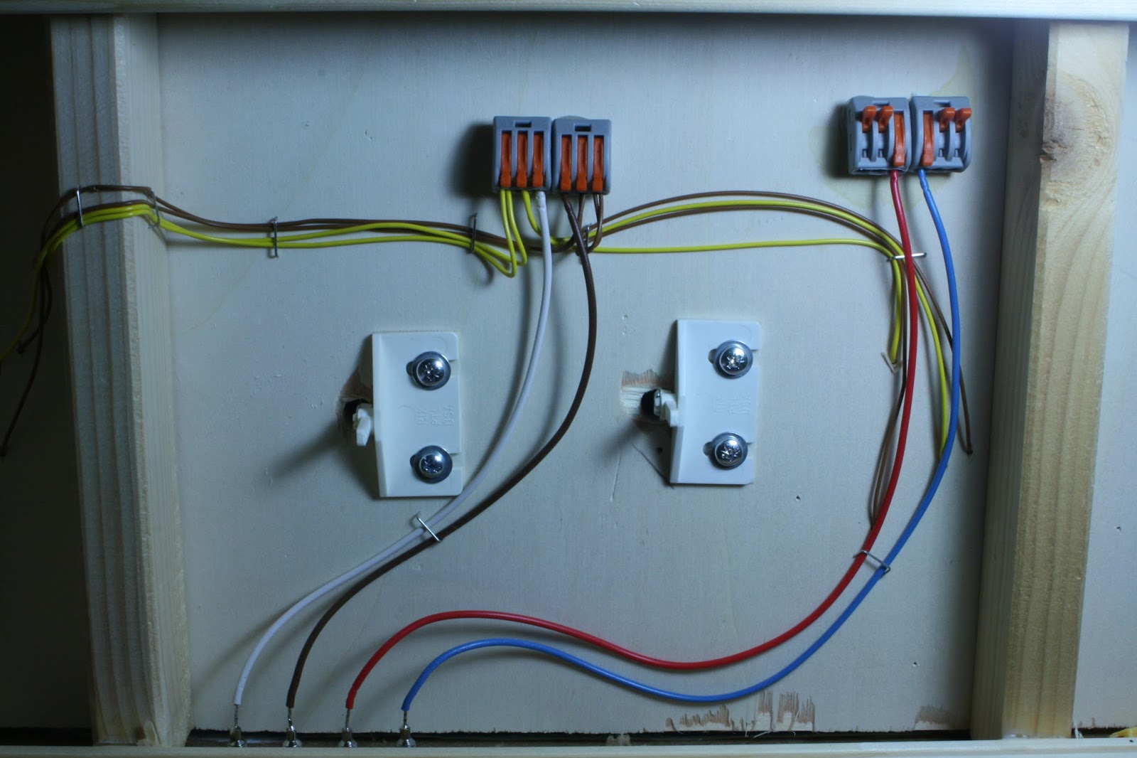
On the underside I shorten the feeder wires and staple them to the board so they don't dangle down. To connect the feeders to the bus wire I use terminal blocks by WAGO. They are standard lighting connector for 2, 3 and 5 conducts. (WAGO SOSElectronic. This link is only for reference. I'm in no way connected to this company) A similar product should be available in your country also. I attach the terminal blocks to the wood surface of the baseboard with hot glue. The advantage here is that I may add wires or rearrange very easily by opening the clip of the respective conduct.


The power supply is fed in from the rear of the box. For reference, the brown and yellow feeders are the trackpower and the red and blue wires are 12-14 VAC current for the lights.

Turnout Control

In an attempt to keep everthing simple, I installed Rix Products PTL (Pivoting Turnout Linkage). They are actuated by choke rods.


Before glueing the turnouts in place I drilled a 10 mm hole into the baseboard for the pivot of the linkage. Positioning of the PTL was made easy by using double sided tape to hold to the underside of the mounting pad.


These turnout controls consist of only four pieces, the mounting pad, the pivot which is clipped to the pad, a piece of piano wire and a small screw to hold the wire to the pivot. Two mounting screws for the pad are also included.


The only thing to take care of is to stick the pivot with the piano wire through the hole in the switch tie correctly from underneath. The PECO turnouts have a spring installed so that the closure rails always close firmly to the stock rails. The double sided tape holds the linkage in place and may be adjusted before drilling the holes for the mounting screws.


I fabricated the choke rods from 2 mm brass tube, 1 mm brass rod and push pins. A piece of brass rod is soldered to one end of the tube, bent 45° and inserted in one of the three holes of the pivot. The tube is then pushed through the fascia and cut to size. The push pin is inserted into the tube and soldered. This is the handle for actuating the pivot and throwing the turnout.


The photo above shows the finished wiring and the turnout controls.

Stay tuned for more progress on the layout.


Saturday, January 23, 2016

APA Micro Layout (Part 5) Box Art for Backdrops

Here's a quickie if you don't know what to do with these nice kit boxes, once the kits are build.
Between the brick backdrop building and the right corner and under the highway bridge, there was a bare blue spot. I first thought of adding a fence and some brushes to hide it, but there would still be a bit of blue sky behind a fence.


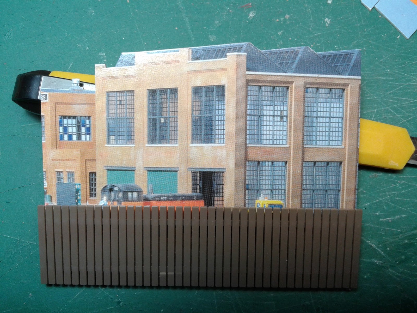
What I needed was some kind of distant building to show behind the fence. I could have cut out a building from an Instant Horizons backdrop painting or paint something myself, when I saw the kit box with the Car Shop parts. Although the picture on the box itself is too large, there are two additional smaller ones on the side that could fit.


Using my metal ruler and a fresh #11 blade in my hobby knife, I trimmed all the excess around the outlines of the pictured building.


Then I shortened the picture to the length of the available space and placed a fence in front to check how it looks.


I used a black marker to darken the edges of the picture.


Then I applied double sided tape to the back of the picture.


That's how it will look when affixed to the backdrop.


With the bridge in place, the fence delimits the shop area and shows another industrial building in the distance. This is a relatively easy way to add some different structures to your background than the usual backdrop buildings found on the market.

The next steps will be trackwork, wiring and turnout control. Stay tuned!


Friday, January 22, 2016

APA Micro Layout (Part 4) Backdrop and tracks

A quick update on my Car Shop Micro Layout.

To break the clear blue sky a bit, I drybrushed some white paint to it. The effect is minimal but looks more realistic than a plain blue backdrop.


I still had to puzzle around with the tracks to locate the turnouts.


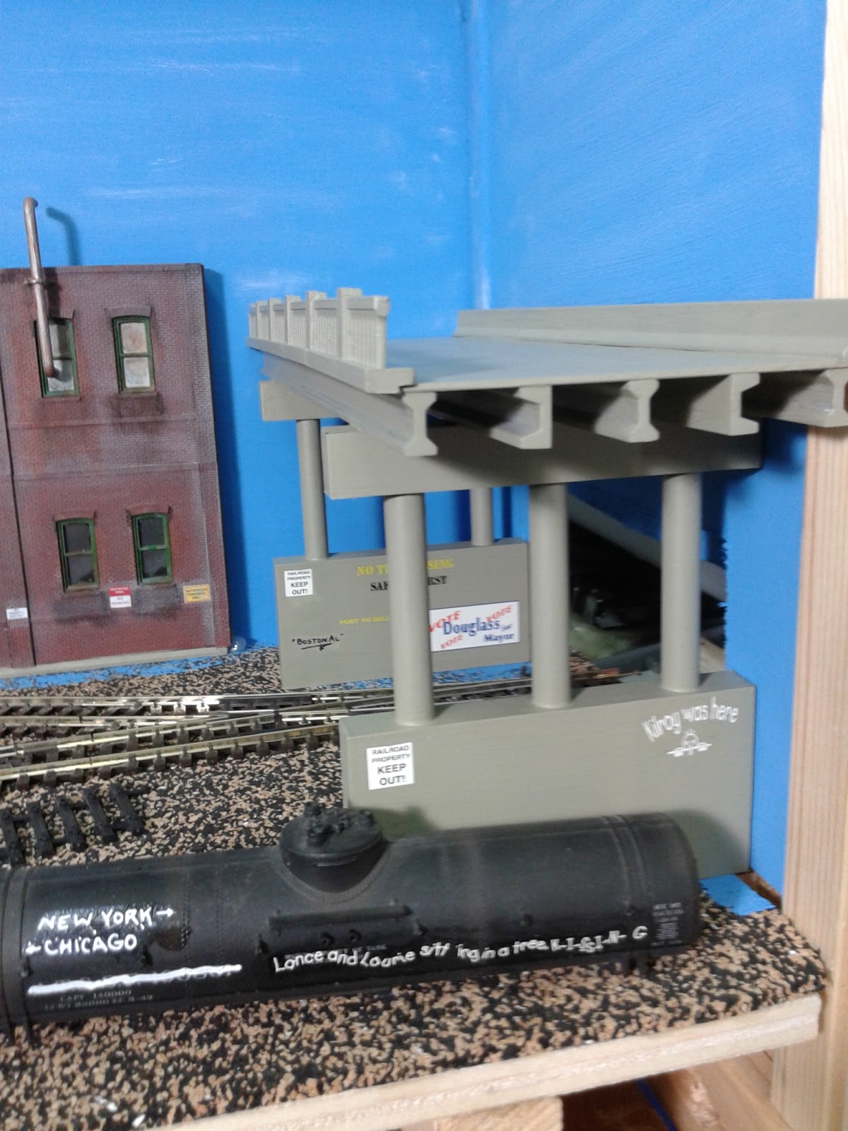
I painted the assembled RIX highway overpass with Floquil concrete color. After thoroughly drying I applied some decals from my kit left-overs. The hole in the backdrop is concealed quite nicely.


I will bury an old tankcar body to act as a water storage tank. The graffiti decals are already applied.

Stay tuned for more updates.

APA Micro Layout (Part 3) Building the Car Shop

The main structure on the micro layout is the car shop. I assembled it from leftover parts from different Walthers kits.


I painted the brick walls Tuscan Red and the concrete parts with Floquil Concrete color. Then I applied various black washes to tone the color down and give it a weathered look.


Two tracks lead inside the building. I removed the rail ties from a short length of PECO code 100 track and glued the rails into the grooves of the concrete floor casting.


The Car Shop building has large industrial windows, through which the interior may be seen. I did not want to paint or apply a black paper behind the window glass to make it less transparent. I remembered that certain glues would craze the styrene or acrylic window glass and wanted to give it a try. Then I thought that Acetone would probably act the same way than glue. (I already attached styrene parts with Acetone when my glue was out). So I painted Acetone to the backside of the window glass. The effect was quite convincing.


From the outside the windows look dirty, so that there are no clear details to be seen, except for the light and probably the shadows of the items inside.


To make the roof removalbe I had to leave the wires long enough so they keep dangling down, but becfause of the crazed windows they won't be seen.


I weathered the concrete floor with burnt umber and burnt sienna pigments, diluted in some isopropyl alcohol. I also applied a black wash to simulate a well used floor with dirt, rust and oil stains.


Here's the finished Car Shop with the brick workshop. To the left of the Shop I also glued another wall section to act as the recessed part of the car shop. A couple of decals round off this step.

Next will be the right side of the box.

Tuesday, January 19, 2016

APA Micro Layout (Part 2) Building a Shadow Box behind an open door


A building, whether in the foreground or not, is always more interesting if the viewer can see the interior or at least part of it. What's probably easier with foreground buildings, might be more difficult with flat or half relief structures glued to the backdrop.


An open door suggests always that there is something to see behind it or inside the building. My backdrop flat is only 15 mm deep and I wanted to inliven the scene by leaving the loading doors partly open. Whereas the left one is almost closed, the right door could reveal a glimpse inside the factory or loading area. Only painting the opening black will not be realistic because the daylight would always light up the area close to the door.


I browsed my drawers and parts boxes for scrap pieces of styrene to build a shallow box behind the opening, when I came across an empty acrylic box that once protected Kadee wheelsets. The box and lid were thin enough to fit behind the building and thus set back far enough to place some boxes, drums and a Preiser figure on it.


I cut one lid in half and gave it a coat of flat black color from a rattle can.


After the paint had dried I glued the tiny shadow box behind the loading door opening.


A pair of drums and a wooden box frame a Preiser truck driver. By pure coincidence I had glued the door just right so that the left arm of the figure suggests pushing up the roll door.


The black background already looked right and gave the scene some life until a friend suggested not to leave it black but to glue a picture with various cargo instead.


He sent me the picture above. I resized and printed it out on normal paper. Then I applied it to the back of the shadowbox and placed the detaisl in front again. Now the scene has life.  


Thanks for reading and stay tuned for more.


Friday, January 15, 2016

APA Micro Layout (Part 1) MIBA Contest layout

For the APA Project layout that we presented at the 5th US Convention in Rodgau last October, I had several more APA Boxes from IKEA left.
These came in handy for the upcoming Micro Layout contest organized by MIBA, one of Germany's best Modelrailroading Magazines. The rules state that for HO, the layout shall not be larger than 70 cm x 30 cm. The same size may be used for a fiddle yard. The APA box measures L70 x W39 x H29.
I use the box sideways, so that I have a height of 39 cm and a depth of 29 cm. The MDF sheets for the sides are arranged in a slightly different way as I don't need the bottom sheet because there will be a 10 mm plywood subroadbed. The MDF is cut to yield a small valance and fascia to hide the light fixture on top and the gap between the subroadbed and the bottom of the box. The separate lid will be attached with hinges to fold down when the layout is not in use.


There is not much room in the box for a lot of track. On the other hand I want a layout that offers at least a minimum of operational possibilities. After browsing through the excellent Micro Layout site of the late Carl Arendt (www.carendt.com) I quickly set on a theme representing a Car Shop with an Inglenook track arrangement.


I test fitted some tracks and turnouts in the box to see what could be done and my enthusiasm faded for the first time. None of my usually used turnouts satisfied me. They were all too long. My son has a PECO Starter set with Setrack turnouts and sectional track. Although these turnouts have really tight diverging radii they would fit the bill. I would use a small switcher anyway, so this would not be a major problem. This way I could build a condensed 3-2-2 Inglenook like Carl Arendt proposed some years ago as an alternative to the standard 5-3-3 version.
 

It was also clear that I had to scratchbuild or at least kitbash all the structures used. Fortunately I have an extensive spare parts box(es) with all kinds of leftover bits and pieces ranging from windows to entire wall sections. The modular walls from Walthers and DPM will also be used to create some background buildings.


Luckily I had a leftover from the Walthers Car Shop that I could use as the main building on the layout. Two tracks lead to the inside and even the spacing of the short turnouts matches with the spacing of the track in the building. The DPM wall sections make it very easy to adapt the length of the building to the available space.


The exit/entrance of the box needs to be concealed. The most common scenic elements are either a tunnel portal, which in my case would not be appropriate, or a bridge with abutments which frame the hole in the side backdrop. I choose the RIX highway bridge. It has nice concrete abutments or legs with the lower part being almost 6 cm high. They hide the hole quite well.


The bridge deck has two lanes, but I will use them as a double lane highway and probably use a second bridge on the fiddle yard box for the opposite direction.


Before I started to fit the structures I painted the backdrop with a sky blue color.


Finally a first setup of the main structures to give a feel of the finished scene. The hole is well covered under the bridge.

Stay tuned for the next installment.