It's been a while since I went to shows with a layout, so I thought it would be time to build a new switching layout to take out to train shows or at the club. So here's the steps from building the box to the finished layout.
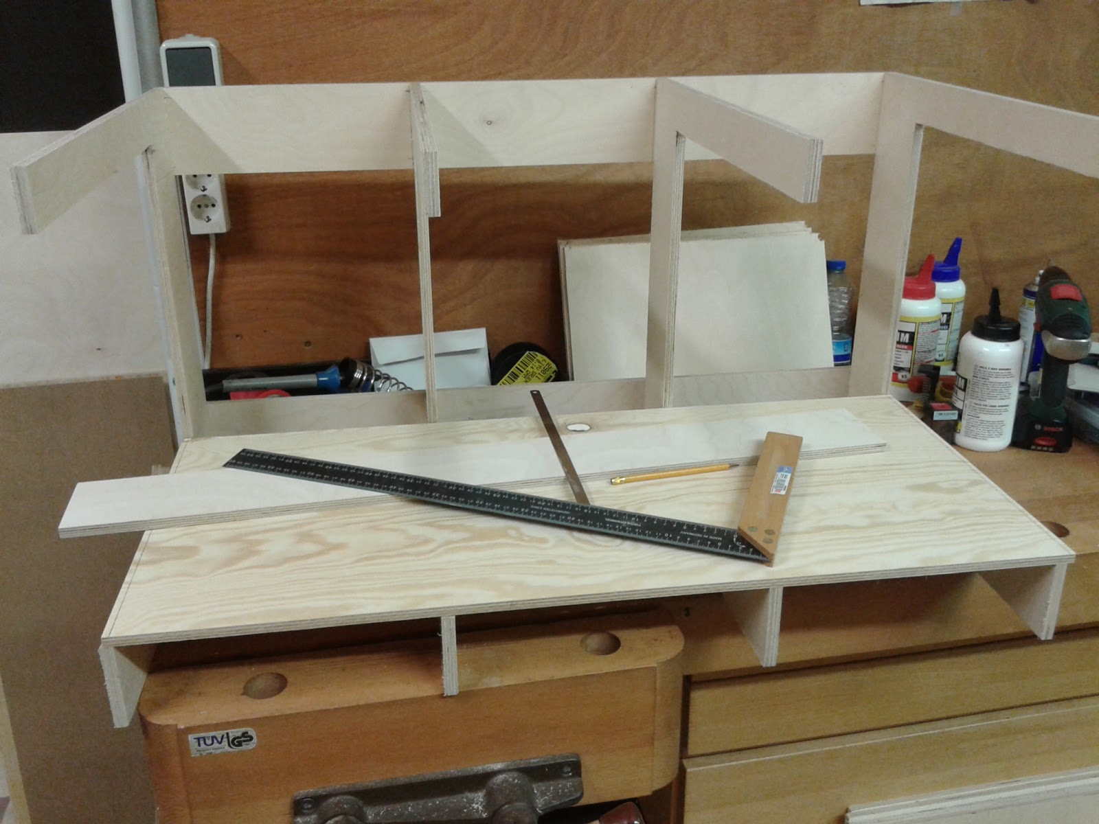
My layout segments basically consist of four C-shaped five-ply wooden brackets, spaced equally to the desired length of the box. My boxes are 90 cm long. The depth is 50 cm with a useable subroadbed of 40 cm.

The most critical part of the assembly is keeping everything square. This led to the design of my lasercut C-brackets on sale at Trackside Miniatures

The brackets are held together with the subroadbed, two longitudinal boards on the back plus the valence and fascia boards. A piece of 3mm MDF is used for the backdrop


The recessed valence hides the lighting fixtures.


After sketching the track plan on the subroad bed I cut cork sheets to size and glued them down over the drawing.

The track arrangement is based on the all-time favorite Box Street design by Jack Throllope

When laying track I always screw the layout segments together and lay the tracks. At the joints where the tracks cross the edge I drill 2 mm pilot holes under the rails and insert short brass screws. I clean the screw heads with a few passes with a metal file. Then I heat the screws with a soldering iron and apply a liberal amount of solder to the head.

After all screw heads are tinned, I lay the tracks across the edge. I need to remove a couple of plastic ties where the rails touch the screw heads. I glue my track either with silicon caulk or carpenters white glue. After the glue has dried I heat one screw head and the respective rail with a soldering iron and apply more solder if necessary. When the rails have cooled down I separate the layout sections by cutting the rails either with a razor saw or a cut-off disk in my rotary tool.
The soldered railheads are very sturdy and easy to align during set-up.
To speed up the process I now also use pattern makers alignment dowels in the end boards. This makes aligning the tracks obsolete.

The back side of the segment reveals the upper and lower boards. There are at least 10 cm between the rear of the backdrop and the back of the box. Plenty of room for hiding the power cords from the lighting fixtures, mounting transformers or power supplies etc.

Before attaching the turnouts I drilled 10 mm holes in the baseboard for the actuating pins of the turnout motors. I used left-overs from my home layout, two Blue Point switch machines and five RixProducts Pivoting Turnout Linkage (#628-0006). The Blue Point Switch Machine is actuated by a simple push rod to the layout's fascia. The adjustable throw rod holds the switch points in positive contact with the running rails to prevent derailments. A DPDT snap-action toggle switch inside the compact plastic housing changes electrical connections to the turnout frog to prevent stalling of locomotives.

Both the Blue Point switch machines and the Rix Pivoting Linkage are push rod actuated and install with two wood screws under the baseboard. The actuating pin is pushed through the hole in the switch tie. A bit of individual adjustment might be needed.

To complete the track-laying process I soldered feeder wires to every rail section, which means that every piece of rail between two rail joiners gets a separate feeder wire. From experience I learned that temperature changes, humidity and dirt and grime from operation has a negative effect on conductivity. The current flow from one rail section to the other through a rail joiner might be interupted after a while. And believe me, it always occurs at a show, when your layout is surrounded by visitors, when a locomotive stalls or the engine sound starts up again because of bad power supply.
Well that's it for now. Keep watching for updates
