Translate

Friday, February 12, 2021

Building a cheap electric static grass applicator

Standing grass is a very realistic scenic feature on every train layout or diorama. Unless you are really building large layouts professionally, you don't need one of these expensive tools which quickly cost in the 100 Euro range. That's my opinion and the bucks saved can be invested into more models. So, if you want to know how to save money without missing the opportunity of having good looking grass on your layout, keep on reading. I'll show you in a couple of steps how to do it.


There are multiple designs of electric fly swatters, so it doesn't matter which one you choose. The blade will be removed anyway. The electronics inside is always the same. Look for a model where the two halves are screwed together. Otherwise you will destroy the handle.


The fly-swatter consists of a handle to which the swatter is attached with a couple of screws. When unscrewing the two halves the swatter may be detached from the handle. A small electronic board provides the high voltage needed. I detached the two wires and discarded the swatter.

The biggest problem consisted in finding a plastic sieve with a metal mesh. Any other metal sieve would also work, but then the danger of accidentally touching the sieve and getting an electric shock would be higher.

I shortened and drilled two holes in the handle to fit over the two pins that held the swatter before. This could be different, depending on what swatter you have. A bit of improvisation is advisable. 


 I soldered one of the wires to the mesh.


Then I lengthened the other lead with a clamp on one end. This is the ground wire, which will be clamped to a screw or nail inserted into the scenery.


To avoid using batteries, I soldered two wires to the battery contacts to power the unit with a external power pack.


I bought a 3V / 1 Amp power supply for less than 3 Euros and connected it to the wire using a male and female plug.


My power cord is about 2 meters long, which is enough to move around freely.


I attach the ground clamp to a screw, inserted in the center of my workspace, where I want to plant my static grass.


The advantage over an applicator with a pot is that you may reach lower areas easily.


Nevertheless I could not resist to buy one of the cheaper offerings with a large pot and two different styles of mesh. This one makes applying longer static grass easier. Next I will change it to external power also.


The small sieve is ideal for the short 2mm fibers


Here is an example of static grass applied to seaweed for bushes and in tree making.


My first attempts with static grass application.


DISCLAIMER: Be aware that this electric device may cause an electric shock. If you build it, you use it under your own responsibility.

Friday, January 17, 2020

Building a switching layout (Part 9) The Yard addition

My switching layout is operational for two years now. I haven't shown it at many shows since, due to time issues. Last autumn I thought that it would be time to attend a couple of shows in France and Germany for the upcoming month. So my first appearance was at the RAMMA Show in Sedan in mid-october 2019. Although I enjoyed operating the layout I found that something was missing to my enjoyment. A neighboring layout almost had the same size as mine, but he had continuous running through an oval with a narrow yard, connected to his layout. My layout only has a short cassette which serves as a drill track for a locomotive and only one (!) car. In fact I only switch the same cars over and over again, except when the big 0-5-0 comes and swaps some cars.


Shortly after the Sedan Show, I headed to my local lumber yard and bought me the required plywood sheets for my new extension of the layout. The days after the show I already made plans how the extension would look like. With measurements on hand, I ordered the sheets cut up, so that I only had to assemble the different segments.


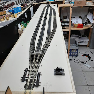
The layout consists of two 90cm (approx. 3 feet) segments, so I build the boxes for the yard to match their size. As I adopted the 90 cm length as a standard for my future show layouts, the yard and future oval will always match whatever layout I would use.


The yard will have a total length of three segments. These will not be needed with my actual switching layout, so I concentrated on only two segments. To save space I used a PECO medium radius 3-way turnout on each side of the yard.


This minimal configuration gives me plenty of storage space to turnover my rolling stock during operations.


I powered the turnouts with surface mounted motors for easy maintenance. Two power the motors I used PECO switches. To install the switches, I had to drill and cut appropriate holes into the baseboard.


 After the wiring was finished, I attached 3mm MDF boards to the sides of the segments. These extend 3cm above the baseboard and prevent rolling stock from falling off the sides. The yard will not be scenicked and its only purpose is to store locomotives and rolling stock on and beside the tracks.


The yard sections rest on a 30 cm deep IVAR shelf from IKEA. The shelf boards give me additional storage space for boxes and stuff needed.


When using the yard as an extension to my switching layout, the original cassettes serves as drill track for a locomotive at the end of the yard. To save space, the 3-way turnouts are located at the edge of the segments, so the cassette is very useful here.


To save on set-up time I installed alignment dowels on all of my segments. To allow multiple configurations I copied the location of the dowels on the cassette to the curve as well as the straight yard sections. Now it's possible to set the layout up in a straight line, as a U or inverted C or as an L, depending on the available space at a show.


With continuous running in mind, I chose to use a 20" radius for the curve. This is tight, I know, but with short switchers and freight cars, the tight radius curve will be no problem.

The new configuration was tested at two shows in December 2019. Some minor issues were corrected and some improvements made and now the layout is ready for the next upcoming shows in 2020 and beyond.


I spent the days between Christmas Dinner and New Year's Eve Dinner to build the third yard segment, which may be inserted in the center of the yard. This, of course in anticipation of the run-around situation for the next show layout.


To avoid tearing up the tracks at the edges of the segments, I always solder the rails to screw heads and cut them later. This makes for a perfect alignment and together with the alignment dowels on the segments I've never had derailment problems.

Stay tuned for more updates.


Thursday, January 2, 2020

Athearn Boxcar improvement

Despite the many beautiful ready-to-run rolling stock available nowadays, I am still a big fan of the old Athearn Blue Box and Roundhouse (Model Die Casting) kits. Many can still be found unbuild, but at swap meets or from various Facebook Sales Pages, some are already built and more or less refined.


Recently I happened to acquire a 50' boxcar, among others, which was already assembled and upgraded with Kadee couplers and metal wheelsets, probably from Intermountain.


The car had been assembled following the instructions with the horn hook couplers replaced with Kadee's and the original wheelsets with better running metal sets. I must admit, on this car the metal coupler pocket clips had been mounted correctly. I simply hate them, because, for whatever reason, I never managed to get them on straight. After a while, the clip always fell off or the coupler did not sit correctly and drooped. 


Anyway, I disassembled the car into its basic components, which are only a few (body, floor, underframe, weight, and trucks)


With a small screwdriver, I unclamped the metal clip and the coupler came loose.


These early kits always have a lot of flash from the molding process, which prevents the parts from fitting flush. This was the case here with the underframe. A few passes with a sanding stick is a quick remedy to this.


Next, the coupler pockets had to go. This is quite easy using a razor saw.


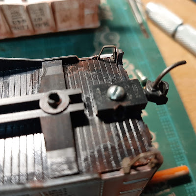
Another step I always do on boxcars, turning the floor. Normally the boarded side goes up into the body. On boxcars with opening doors, this might be a nice detail, but as the boxcars usually run with doors closed, this isn't visible either. On the 50 footers I bought, the doors cannot be opened. By turning the boarded side down, the floor really looks like the real thing, because that's what you normally see from underneath. I simply screw the underframe to the turned floor and for a permanent fix, I also glue the frame to it.


Then I glue the lid of the Kadee draft gearbox to the floor, taking care to center it. After the glue has set, using the center hole as a guide, I drill and tap for a 2-56 screw.


Then I assemble the draft gear box and secure it with a screw.
 

I attached the metal weight to the floor using double-sided tape. This is no permanent fix, believe me. A small piece of leftover styrene, drilled to fit over the "original" bolster pin and then secured with a few drops of cement will keep the weight in place.


I will never open this car again, so I glued the floor assembly to the body. The clamps make sure that the bond will be permanent.


A final detail, which is quickly added consists of replacing the oversized steps. I simply snapped the original steps off using a small sprue cutter. Don't bother to drill into the sides! Chances are that your drill slips. I drilled immediately behind the side, next to the floor and inserted A-Line wire steps. These are not only smaller, but also sturdy.

Remember, this is not a contest model. My primary goal is to have a reliable car intended for operation. Nevertheless, some of these tips may also be a base for a better-looking model.

Stay tuned. In a future installment, I'll show you a quick weathering technique. 


Tuesday, October 8, 2019

Building a switching layout (Part 8) Finished

Below is a stitched together image of the switching layout.


The two pictures below show the layout at its first appearance at the US-Convention in Rodgau/Germany back in 2017.


Below are some of the scenes I created. There are still some details to be added.


I am looking forward to meet you at one of the shows in Europe.