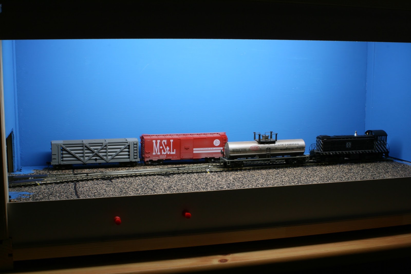
After all the track and turnouts have been wired, I hooked up a simple transformer and made a couple of passes through all the turnouts and spurs. I used one of my analog Walthers/Life Like P1K Alcos with one 50' Boxcar to see if there are no dead rails.
I laid all the track and turnouts on cork roadbed, not for sound reduction but only to get the track raised above ground level. The wider strips of cork will be my roads.
I did not build the tracks to fit along the structures that I would use. This would be too simple. Guess I'm joking here. I already regret my decision. This implies that I have to build all my structures to suit my existing track arrangement. It's like on the prototype.
To start with, I measured my available spaces between or next to the tracks and fashioned paper templates with the footprints of the future buildings.
Except for the footprints, at this stage of construction, I had no clue of what buildings I would put there. I relied completely on my considerable stash of scratchbuilding material and leftovers from previous kits.
In the meanwhile I filled the screw heads and sanded the facia and valance smooth in preparation of the painting. The backdrop already received a coat of sky blue. To some the sky might be too "blue", but most of what you see there will be covered with backdrop buildings anyway. I like the strong blue color because the sky is actually blue on the photos and not grey or white with a backdrop that is painted with a lighter color.
The access to the staging yard cassette will also be hidden by a corner building and a highway bridge.
Most spur tracks will only hold one car plus engine.
A bird's eye perspective of the layout. The lighting fixtures are behind the upper valance.
You don't need as many clamps to hold the sideboard until the glue has dried, but I had enough of them at the club, so I probably did a bit of overkill. ;)
That's the staging area which basically hides a turnout to form a runaround. Because of the turnout, there is not enough room left to switch cars, so I added a short (2 car length) extension.
I usually paint my fascia and valance black. It makes a better contrast with the lighted interior of the box. This is the left side view of the layout....
..and here the right side. I also recessed the turnout controls to avoid damage during transport and operation.
Thanks for following and now it's time to build some structures.
On this blog I want to share my other modeling escapes not directly related to my home layout. It encompasses everything from 1/87 (HO) over 1/72 to 1/35. Another passion is military modeling in 1/72 and 1/35 with an emphasis on dioramas. Also Tips and Tricks that I found and learned along the way, are shown on this page. Enjoy because Modeling is Fun.
Translate
Monday, August 29, 2016
Friday, August 19, 2016
Building a switching layout (Part 1) The Boxes and laying track
It's been a while since I went to shows with a layout, so I thought it would be time to build a new switching layout to take out to train shows or at the club. So here's the steps from building the box to the finished layout.
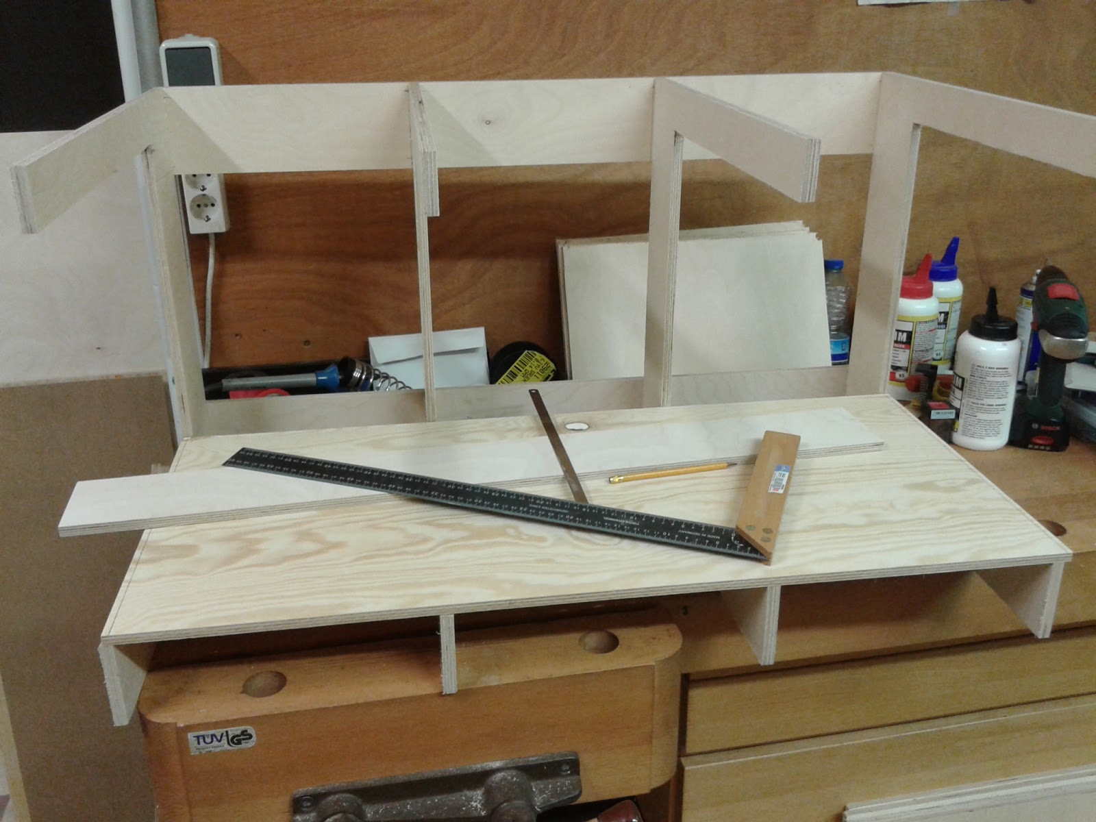
My layout segments basically consist of four C-shaped five-ply wooden brackets, spaced equally to the desired length of the box. My boxes are 90 cm long. The depth is 50 cm with a useable subroadbed of 40 cm.
The most critical part of the assembly is keeping everything square. This led to the design of my lasercut C-brackets on sale at Trackside Miniatures
The brackets are held together with the subroadbed, two longitudinal boards on the back plus the valence and fascia boards. A piece of 3mm MDF is used for the backdrop
The recessed valence hides the lighting fixtures.
After sketching the track plan on the subroad bed I cut cork sheets to size and glued them down over the drawing.
The track arrangement is based on the all-time favorite Box Street design by Jack Throllope
When laying track I always screw the layout segments together and lay the tracks. At the joints where the tracks cross the edge I drill 2 mm pilot holes under the rails and insert short brass screws. I clean the screw heads with a few passes with a metal file. Then I heat the screws with a soldering iron and apply a liberal amount of solder to the head.
After all screw heads are tinned, I lay the tracks across the edge. I need to remove a couple of plastic ties where the rails touch the screw heads. I glue my track either with silicon caulk or carpenters white glue. After the glue has dried I heat one screw head and the respective rail with a soldering iron and apply more solder if necessary. When the rails have cooled down I separate the layout sections by cutting the rails either with a razor saw or a cut-off disk in my rotary tool.
The soldered railheads are very sturdy and easy to align during set-up.
To speed up the process I now also use pattern makers alignment dowels in the end boards. This makes aligning the tracks obsolete.
The back side of the segment reveals the upper and lower boards. There are at least 10 cm between the rear of the backdrop and the back of the box. Plenty of room for hiding the power cords from the lighting fixtures, mounting transformers or power supplies etc.
Before attaching the turnouts I drilled 10 mm holes in the baseboard for the actuating pins of the turnout motors. I used left-overs from my home layout, two Blue Point switch machines and five RixProducts Pivoting Turnout Linkage (#628-0006). The Blue Point Switch Machine is actuated by a simple push rod to the layout's fascia. The adjustable throw rod holds the switch points in positive contact with the running rails to prevent derailments. A DPDT snap-action toggle switch inside the compact plastic housing changes electrical connections to the turnout frog to prevent stalling of locomotives.
Both the Blue Point switch machines and the Rix Pivoting Linkage are push rod actuated and install with two wood screws under the baseboard. The actuating pin is pushed through the hole in the switch tie. A bit of individual adjustment might be needed.
To complete the track-laying process I soldered feeder wires to every rail section, which means that every piece of rail between two rail joiners gets a separate feeder wire. From experience I learned that temperature changes, humidity and dirt and grime from operation has a negative effect on conductivity. The current flow from one rail section to the other through a rail joiner might be interupted after a while. And believe me, it always occurs at a show, when your layout is surrounded by visitors, when a locomotive stalls or the engine sound starts up again because of bad power supply.
Well that's it for now. Keep watching for updates
Tuesday, August 2, 2016
APA Micro Layout (Part 14) - Detailing the Fiddle Yard (Part 3)
Some time ago I had built a gluing jig to assemble the Walthers chain link fence. These plastic poles are OK on a permanent layout out of reach or accidental damage, but on my switching layout they would be too delicate because I need to reach inside the layout to uncouple cars.
A sturdier version of the fence is needed. So I replaced the plastic poles with brass wire. I used the Walthers instructions to construct the fence and instead of gluing the wires to the poles, I soldered them for additional strength.
The photo above shows a close-up view of the fence assembly. Before attaching the mesh I painted the fence silver using a rattle can.
I attached the fine mesh from the kit and glued it to the fence assembly using Alene's tacky glue.
The ice storage box comes from a Classic Miniatures ice truck, mounted on a GC Laser wooden platform.
A sturdier version of the fence is needed. So I replaced the plastic poles with brass wire. I used the Walthers instructions to construct the fence and instead of gluing the wires to the poles, I soldered them for additional strength.
The photo above shows a close-up view of the fence assembly. Before attaching the mesh I painted the fence silver using a rattle can.
I attached the fine mesh from the kit and glued it to the fence assembly using Alene's tacky glue.
The ice storage box comes from a Classic Miniatures ice truck, mounted on a GC Laser wooden platform.
Tuesday, May 31, 2016
APA Micro Layout (Part 13) - Detailing the Fiddle Yard (Part 2)
For the background I opted again for a mix of half relief structures and box art images from Walthers kit boxes.
I've cut the box art pictures out and placed them against the blue backdrop.
They blend in well with the "real" structures. To hide the seam between backdrop and scenery, I glued a concrete fence between the brick structure and the engine shop.
The engine shop received a first coat of black wash.
I scribed the styrene sheet to represent expansion joints and painted the whole area with Floquil (Yes, I still have some left) Concrete color. To give the area a weathered look, I also applied a black wash.
The background building was a leftover from another layout. I covered the middle and lower window openings with brick sheet as well as the entrance.
I applied a couple of decals and gave the structure several coats of black and concrete washes.
The box art images give an amazing 3-D effect
The structures and basic scenery are installed. Now it's time for the final detailling of the scene.
I've cut the box art pictures out and placed them against the blue backdrop.
They blend in well with the "real" structures. To hide the seam between backdrop and scenery, I glued a concrete fence between the brick structure and the engine shop.
The engine shop received a first coat of black wash.
I scribed the styrene sheet to represent expansion joints and painted the whole area with Floquil (Yes, I still have some left) Concrete color. To give the area a weathered look, I also applied a black wash.
The background building was a leftover from another layout. I covered the middle and lower window openings with brick sheet as well as the entrance.
I applied a couple of decals and gave the structure several coats of black and concrete washes.
The box art images give an amazing 3-D effect
The structures and basic scenery are installed. Now it's time for the final detailling of the scene.
APA Micro Layout (Part 12) - Detailing the fiddle yard (part 1)
The rules for the micro layout contest required that the fiddle yard could not be larger than the actual layout. It also didn't have to be scenicked. As I plan to operate it at shows, the bare fiddle yard was no option. So I decided to fit in a couple of structures and to add scenery.
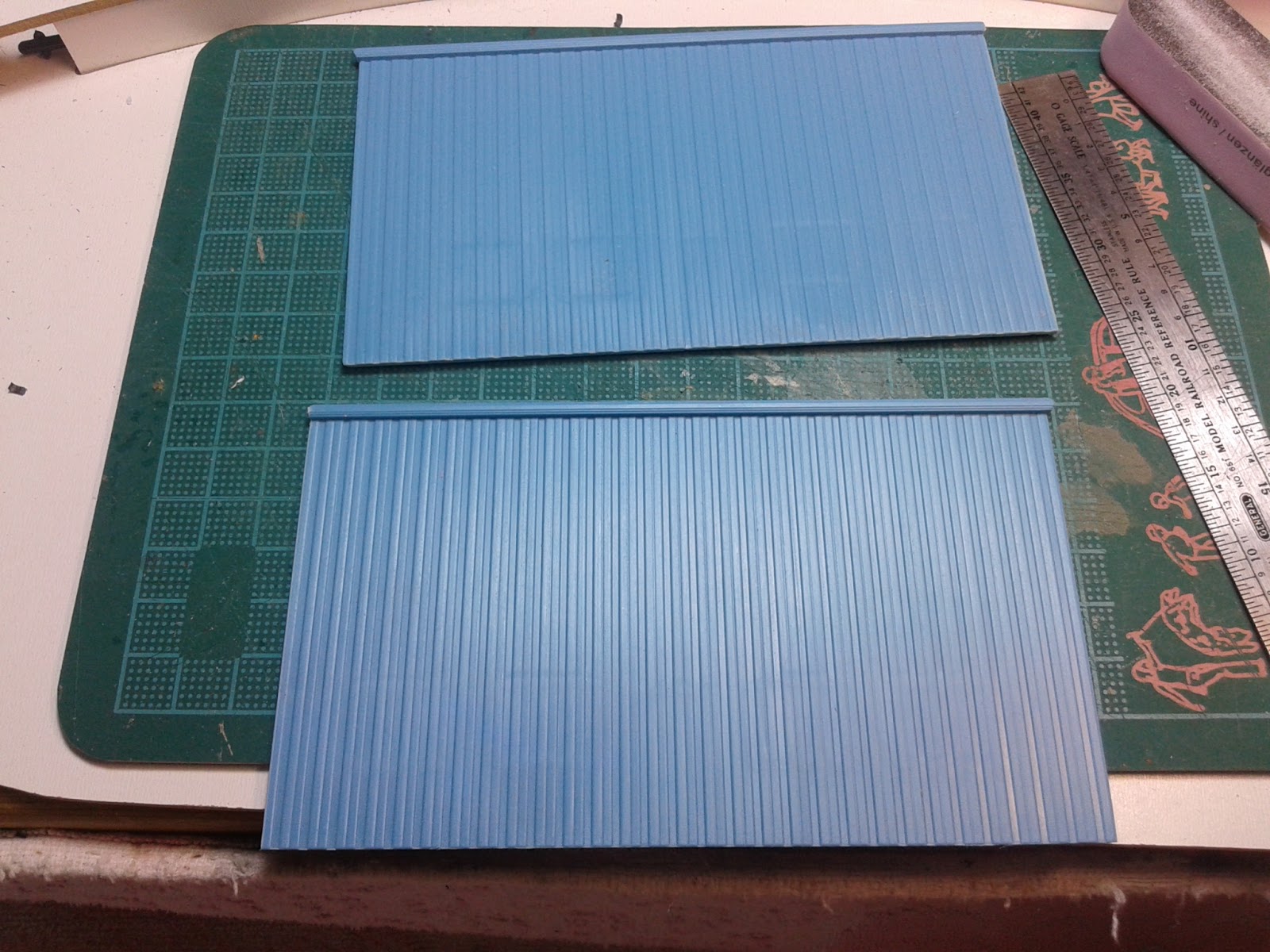
While I was shuffling around with the components at hand, I quickly realised that the addition of a cassette outside the box would give me additional switching possibilities. So I cut an opening to the rights side wall as well.
The left side of the box was concealed with another highway bridge which represents the opposite direction of the two-lane overpass
The right hand exit/entrance would be hidden by a two-stall engine house from Rix Products
The two tracks diverging from the crossing will act as runaround track for the layout. I also may change motive power or rolling stock with this connection.
The engine house will only have half its length.
To the edge of the layout, I glued Evergreen styrene sheets to represent a concrete unloading area.
I used one of the spare wall sections and cut a loading door opening. I lined the opning with Evergreen styrene angles to represent the sash.
I test fitted all the components before gluing to see how the finished scene would look like.
While I was shuffling around with the components at hand, I quickly realised that the addition of a cassette outside the box would give me additional switching possibilities. So I cut an opening to the rights side wall as well.
The left side of the box was concealed with another highway bridge which represents the opposite direction of the two-lane overpass
The right hand exit/entrance would be hidden by a two-stall engine house from Rix Products
The two tracks diverging from the crossing will act as runaround track for the layout. I also may change motive power or rolling stock with this connection.
The engine house will only have half its length.
To the edge of the layout, I glued Evergreen styrene sheets to represent a concrete unloading area.
I used one of the spare wall sections and cut a loading door opening. I lined the opning with Evergreen styrene angles to represent the sash.
I test fitted all the components before gluing to see how the finished scene would look like.
A loading ramp from the scrap box would complete the structure.
Stay tuned for the next step in finishing the scene.
Wednesday, February 24, 2016
APA Micro Layout (Part 11) Operation
After three months of building, my Micro Layout for the contest of the german modelrailroad magazine MIBA is finally finished.
The track arrangement is a so-called Inglenook switching puzzle. More details about building and operating this kind of layout may be found on Adian Wymann's The Model Railways Shunting Puzzles Website.
The photo above shows the entire layout in a space of 70 x 30 cm (2'4" x 1')
The fiddle yard has the same dimensions but is not scenicked .... yet. The rules for the contest only mentioned a fiddle yard, the same size as the layout, attached to one side or half the size on each side. The two tracks through the crossing are the drill tracks.
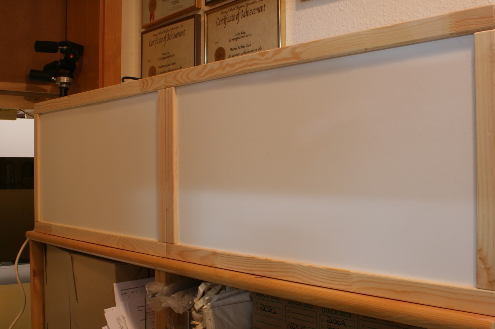
The advantage of the APA boxes is that they are real boxes with a lid. I used the boxes sideways so there is more height for the layout. The box lids serve a double purpose, dust and damage protection.
The interior of the boxes are lighted with one fluorescent tube each, attached to the valance.
As for operation, I kept it simple. The minimal Inglenook that I have calls for five cars, placed on random spots on the layout. Three cars are to be switched into a departing train. There are random car generators on the internet to select the cars, but this involves a computer next to the layout. I simply added one car for total of six. I also choose cars in different colors. I painted a wooden dice with the same colors than the cars. This is my random selector. On a sheet of paper I only note the order in which the cars are to be placed behind the locomotive.
At the beginning of an operating session, the six cars are placed randomly on the layout. Now I throw the dice. Then I note the color of the first car. Then the second and the third. Now I switch the cars in the order I have thrown the dice. This implies some challenging switching moves, as the remaining cars must be replaced where they stood initially.
The original Inglenook with a 5-3-3 arrangement generates some 40,000+ configurations. My version still 120. That's enough for some relaxing killing time.
The track arrangement is a so-called Inglenook switching puzzle. More details about building and operating this kind of layout may be found on Adian Wymann's The Model Railways Shunting Puzzles Website.
The photo above shows the entire layout in a space of 70 x 30 cm (2'4" x 1')
The fiddle yard has the same dimensions but is not scenicked .... yet. The rules for the contest only mentioned a fiddle yard, the same size as the layout, attached to one side or half the size on each side. The two tracks through the crossing are the drill tracks.
The advantage of the APA boxes is that they are real boxes with a lid. I used the boxes sideways so there is more height for the layout. The box lids serve a double purpose, dust and damage protection.
The interior of the boxes are lighted with one fluorescent tube each, attached to the valance.
As for operation, I kept it simple. The minimal Inglenook that I have calls for five cars, placed on random spots on the layout. Three cars are to be switched into a departing train. There are random car generators on the internet to select the cars, but this involves a computer next to the layout. I simply added one car for total of six. I also choose cars in different colors. I painted a wooden dice with the same colors than the cars. This is my random selector. On a sheet of paper I only note the order in which the cars are to be placed behind the locomotive.
At the beginning of an operating session, the six cars are placed randomly on the layout. Now I throw the dice. Then I note the color of the first car. Then the second and the third. Now I switch the cars in the order I have thrown the dice. This implies some challenging switching moves, as the remaining cars must be replaced where they stood initially.
The original Inglenook with a 5-3-3 arrangement generates some 40,000+ configurations. My version still 120. That's enough for some relaxing killing time.
Subscribe to:
Posts (Atom)